Adapt Hank’s Probe to Other Layouts
Hank’s kit works best on his own lights but it can be made to work with others.
Using Hank’s Kit for 3 over 3 Pads
The Flashing Kit from Hank probe is 4 over 2, but with some extra effort it can also be used with 3 over 3 interfaces. This requires something to make contact with the additional pad on the row with only two pins on the probe. This can be any number of things, but two easy and common ways are:
A pogo pin press fit into a socket Dupont connector on a wire
A multimeter probe lead
Required materials are:
Pogo pins - optional, but useful for crafting the extra probe lead
First connect some jumper wires to the probe from Hank’s kit as follows:
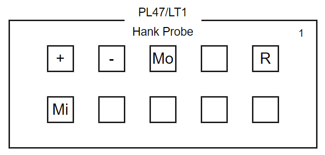
Pins on probe from Hank’s Kit for connecting USBASP
Next, connect the wires from the probe to the USBASP pins following this pattern:
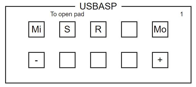
USBASP pins for connecting to probe for 3 over 3, plus the extra lead
Connect the extra lead where indicated. This lead will connect to the open pad on the light that isn’t making contact with the probe from Hank’s kit.
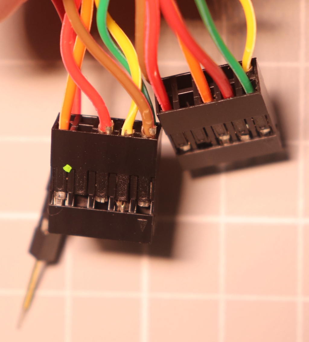
Dupont blocks with wires configured for adapting Hank’s kit to 3 over 3
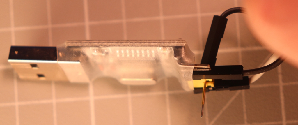
When making contact with the pads, ensure both the probe and the extra lead are aligned and making proper contact.
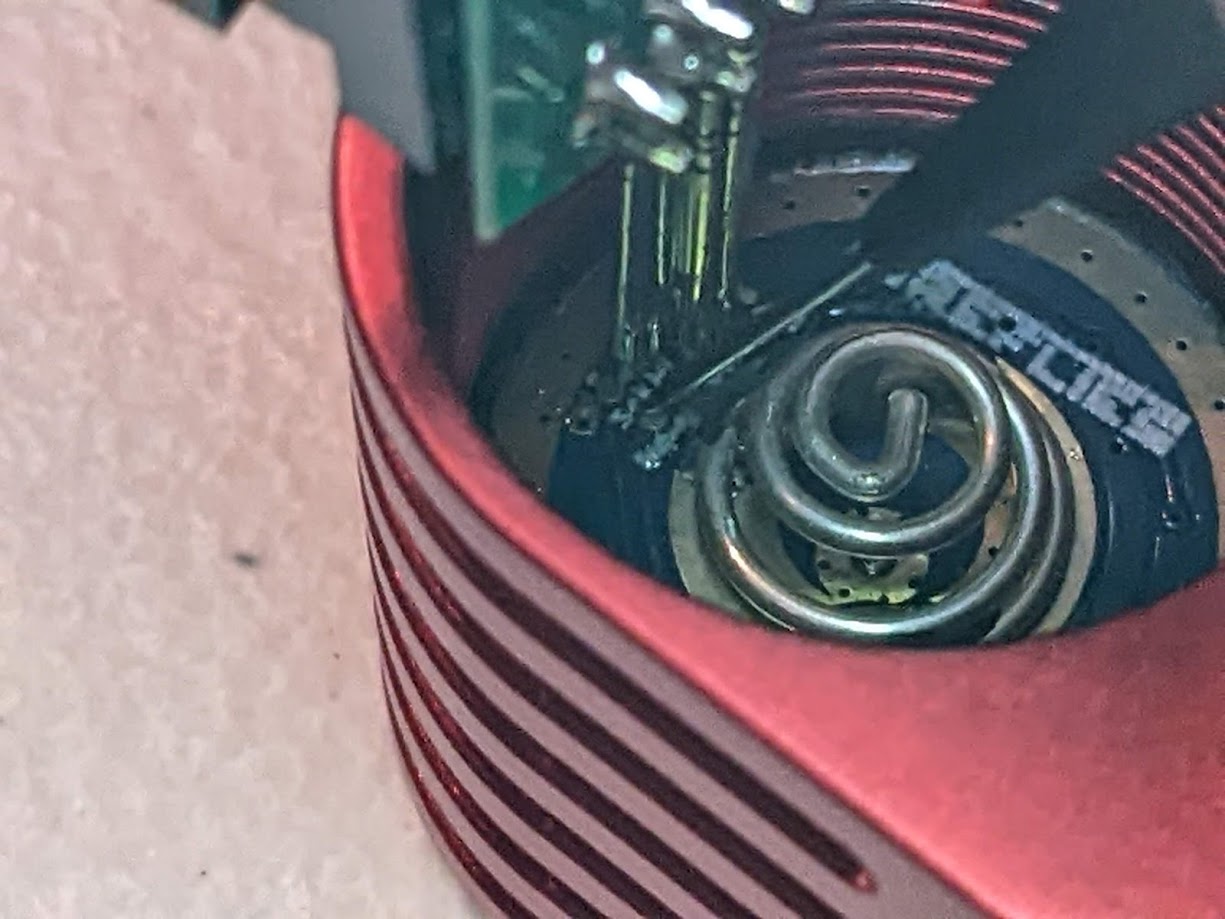
Hank’s Probe and Extra Lead Connected to 3 over 3 Fireflies PL47G2
Using Hank’s Kit for 3 Pad UPDI
The Flashing Kit from Hank probe is 4 over 2, but can easily be used with a 3 pad setup since there are more than 3 pins in a row.
All it takes is:
Jumper wires with Dupont connectors to go from the programmer to the probe on the correct pins.
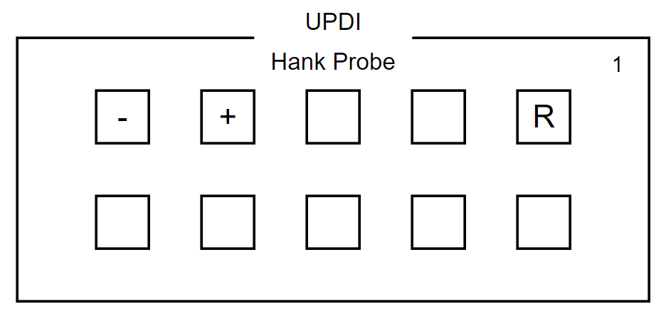
Pins on probe from Hank’s Kit for connecting to CH340
Connect a socket-to-socket jumper wire from
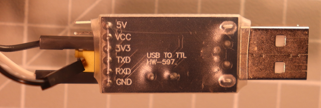
+on the probe toVCCon the CH340 board.Connect a socket-to-socket jumper wire from
-on the probe toGNDon the CH340 board.Connect a socket-to-plug jumper wire from
Ron the probe to bothRXDandTXDon the CH340 board.
The CH340 board linked above has a jumper between RXD and TXD and a plug
Dupont connector can rest in the opening of the jumper and make contact, so it
touches both pins.
Bridging RX and TX on the CH340 Board (Side)
Bridging RX and TX on the CH340 Board (Bottom)
Alternately, some people have chosen to solder the wire to the jumper, or made A
cable to connect both pins, for example. As long as the R contact on the
probe makes good electrical contact with both RXD and TXD it will work.